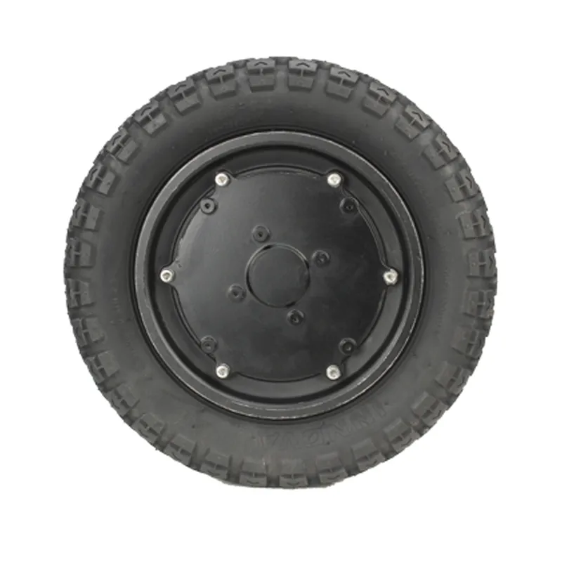
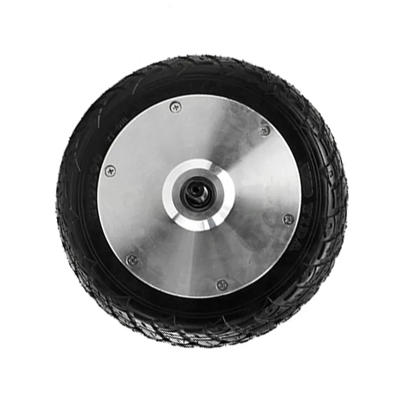
Brushless direct-drive hub motors are well suited to compact electric mobility equipment because the motor is integrated with the wheel and can reduce external transmission components. However, a hub motor that performs reliably at normal travel speed may face significantly different operating conditions during frequent starts, climbing, prolonged low-speed travel, and sustained full-load operation. In these conditions, torque demand can remain high while cooling is limited, increasing the risk of excessive temperature rise and overload.
WINAMICS supports OEMs, equipment manufacturers, and engineering teams with brushless hub motor selection, controller matching, prototype testing, and customized electric drive solutions. Evaluating load, speed, duty cycle, terrain, and thermal conditions before selection helps establish a more appropriate motor and controller solution for the intended equipment.
Direct-drive hub motors generate wheel torque directly, without relying on a conventional reduction gearbox. This structure can simplify the drive arrangement, but it also means the motor must produce the required wheel torque within its own operating range. At low vehicle speed, especially near standstill, the motor may require high current to produce enough torque for acceleration, climbing, or moving a heavy load.
Electrical losses increase as current rises. At the same time, a slowly rotating wheel provides less air movement around the motor than a wheel travelling at higher speed. When high current and reduced cooling occur together for an extended period, heat can accumulate in the motor windings, magnets, cables, connectors, controller, and adjacent wheel components. Thermal performance therefore depends not only on rated motor parameters, but also on the real operating cycle of the equipment.
Repeated acceleration can create repeated peak-current demand. This is common in bumper cars, electric carts, delivery equipment, mobile robots, and equipment operating in confined spaces.
Inclines increase the tractive force needed at the wheel. A loaded vehicle travelling slowly uphill may remain in a high-torque operating condition for longer than expected.
Vehicle mass, cargo weight, passenger load, and rolling resistance all affect continuous torque demand. Higher load may require a different motor, wheel size, or drive configuration.
Equipment that moves slowly for long periods may not benefit from the cooling associated with higher wheel speed, even when the route appears relatively flat.
Overload is not only a question of whether the vehicle can move. It is also a question of whether the electric drive can operate within an appropriate thermal range throughout the intended duty cycle.
| Risk Factor | How It Develops | Selection Consideration |
|---|---|---|
| High motor current | High torque demand at low speed can require higher current. | Review starting torque, climbing torque, current limits, and peak-duration requirements. |
| Limited heat dissipation | Slow wheel rotation and enclosed installation conditions can reduce cooling. | Consider ambient temperature, installation space, wheel construction, and continuous operating time. |
| Controller overload | A controller may repeatedly deliver high phase or battery current under heavy demand. | Match controller current capability and protection settings to the motor and application. |
| System-level stress | Cables, connectors, battery capability, tires, and mechanical mounting can all influence drive behavior. | Evaluate the complete electric drive system rather than selecting the hub motor in isolation. |
Motor power, voltage, speed, and torque values should be interpreted together with the actual working conditions. A selection based only on nominal power or target top speed may not reflect the demand created by a loaded start on a ramp, repeated reversing, soft ground, uneven flooring, or long-duration low-speed operation. The most useful evaluation considers continuous demand, peak demand, peak duration, recovery time, and thermal environment.
Before specifying a brushless direct-drive hub motor, engineering teams can define the application using a structured set of operating inputs:
The motor and controller work as one electric drive system. The controller influences acceleration behavior, current delivery, speed regulation, forward and reverse operation, and protection response. An unsuitable controller setting can allow excessive current demand, create poor low-speed control, or limit usable torque even when the motor itself appears correctly sized.
For low-speed high-torque equipment, controller matching should consider the required control method and the relationship between battery current, phase current, acceleration settings, speed limits, and thermal protection behavior. Protection functions can help reduce stress during abnormal or demanding conditions, but they do not replace correct motor sizing and a realistic assessment of the equipment duty cycle.
Prototype evaluation can help compare the intended application with the actual operating behavior of the drive. Relevant test items may include:
Where standard specifications do not fit the equipment duty cycle, a customized drive solution may be considered. Depending on the application, WINAMICS can discuss motor voltage, power, speed, torque, wheel diameter, tire material, axle structure, installation dimensions, wiring interfaces, brake structure, protection requirements, and controller parameters.
The objective is not simply to specify a larger motor. A suitable solution balances required torque, target speed, wheel size, available voltage, physical integration, controllability, and expected thermal conditions for the equipment.
For equipment expected to operate under frequent starts, climbing, full load, or extended low-speed travel, share the operating profile early in the development process. A clear review of the motor, controller, vehicle load, wheel size, and thermal requirements gives WINAMICS a stronger basis for supporting an appropriate brushless hub motor and integrated electric drive solution.
 Shenzhen Jinhaixin Holdings kart motor 213mm brake disc high-torque motor karting modification
WINAMICS hub motor system evaluation robot hub motor selection light electric vehicle motor matching hub motor controller battery matching
Shenzhen Jinhaixin Holdings drive controller selection criteria system performance control accuracy
Shenzhen Jinhaixin Holdings custom selection low-voltage three-electric system sample validation B2B procurement
Hub motor Brushless hub motor High-performance hub motor Customized motor solutions WINAMICS